
What Is a Floor Brake? Definition and Core Purpose
The Core Definition of a Floor Brake
A floor brake — also widely called a floor lock or equipment floor brake — is a foot-operated, floor-contacting locking device mounted on the base frame of wheeled industrial equipment. Unlike a conventional caster brake that acts on the wheel itself, a floor brake is pressed down by foot to bring a dedicated friction pad directly into contact with the floor surface. As the pedal travels to the bottom of its stroke, the mechanism lifts one corner or one side of the equipment slightly, unloading the casters and transferring the full static load onto the floor pad. When the pedal is released, the spring returns the linkage, the pad lifts away from the floor, and the equipment is free to move again.
In everyday workshop terms, the job of a floor brake is simple to state: casters let equipment move; the floor brake lets it stay put. Once a fully loaded transfer cart arrives at a workstation, a worker steps on the floor brake, and the cart stops rolling, rocking, or drifting — even when parts are unloaded, tools lean against the frame, or operators lean their weight on the tabletop. This clean separation of “move” and “park” functions is why floor brakes have become standard on material carts, inspection benches, assembly stations, and automated equipment supports.
Why Standard Caster Brakes Fall Short
A standard caster brake is designed to hold a wheel still, not to hold the whole machine still. When the brake pedal is pressed, a small shoe contacts the tire tread or the hub, preventing the wheel from rotating. On a smooth, dry, lightly loaded floor this is often enough for a few minutes of parking. But the moment the load grows, the floor becomes uneven, or a lateral push is applied — for example, when a worker slides a heavy drawer open or leans into a fixture — a locked wheel can still skid across the concrete because friction between the tire and the floor is the only thing resisting motion. The wheel is locked, but the equipment as a whole is not.
This is the gap the floor brake exists to close. By bypassing the wheel entirely and pushing a dedicated pad against the floor, it creates a direct, load-bearing friction anchor that does not depend on tire condition, swivel orientation, or floor flatness.
Floor Brake vs. Standard Caster Brake: Key Differences
What a Standard Caster Brake Actually Locks
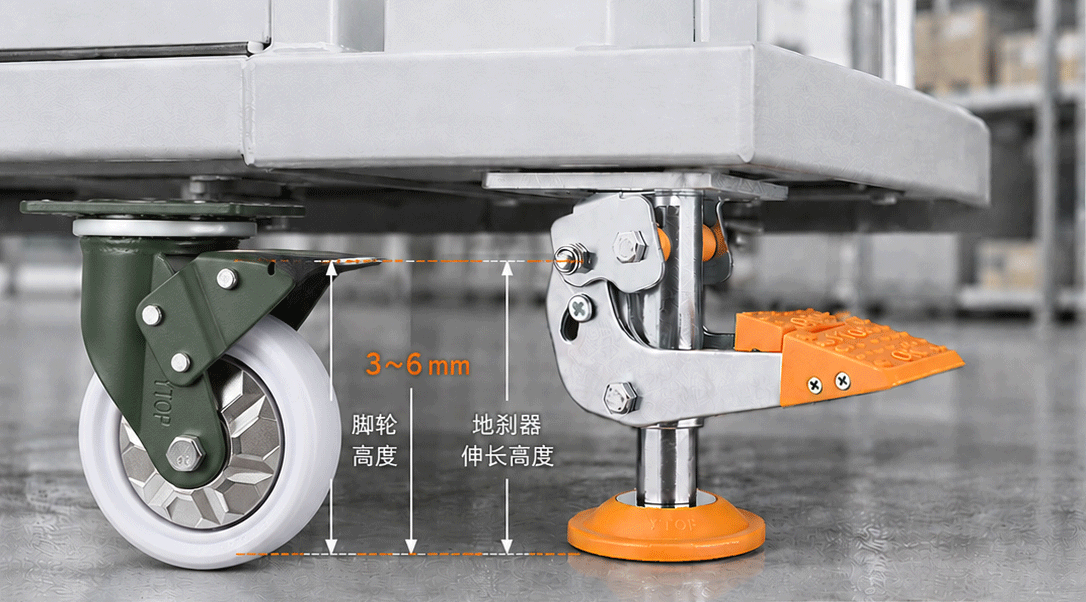
A standard caster brake locks the rotation of the wheel. Its brake pad acts on the tread or the hub, so the wheel cannot spin. Two familiar variants are the side brake, which presses against the tire side, and the total-lock brake, which locks both wheel rotation and swivel. In both designs, however, the contact with the outside world is still the rubber or polyurethane tire, and the holding force is limited by tire-to-floor friction. When the tire is worn down, glazed, or slightly flattened from weeks of static loading, that holding force drops sharply.
Three Problems a Floor Brake Solves
A floor brake addresses three weaknesses that caster brakes commonly cannot:
- 360-degree swivel pedal problem: On universal (swivel) casters, the brake pedal rotates with the wheel fork. After the caster has turned to a random angle, the pedal may face away from the operator or sit awkwardly under the frame, making it hard to reach and step on. A floor brake has a fixed, dedicated pedal on the equipment frame that never moves, so operators can always find it by foot.
- Brake failure on worn wheels: As a caster tire wears, flattens, or becomes glazed, the brake shoe may no longer bite reliably. A floor brake uses its own renewable polyurethane pad, so its holding force does not degrade with tire wear.
- Sliding on uneven or sloped floors: A locked wheel can still skid sideways on uneven, oily, or slightly sloped concrete. A floor brake lifts the equipment onto a wide, high-friction pad that resists lateral movement directly, holding the machine even when the floor is not perfectly flat.
The two devices are therefore complementary, not competing: caster brakes handle deceleration and short holds during transport, while floor brakes handle long-term, load-bearing parking at the workstation. Demanding equipment often carries both, using wheel brakes to slow down on the move and floor brakes to park once in position.
Structural Components of a Floor Brake
Steel Base Plate, Pedal, and Spring Mechanism
A typical floor brake is built around a stamped or welded steel base plate that bolts to the equipment frame through slotted mounting holes. The plate anchors the whole assembly and absorbs the reaction force of the downward pressing load. On top of the plate sits the foot pedal — the operator interface — usually made of forged or thick stamped steel with an anti-slip serrated surface so that a work boot can actuate it reliably even when oily or damp.
Between the pedal and the pad sits a spring and linkage assembly. The spring stores energy when the pedal is depressed, drives the pad downward, and then returns the pedal to the raised (free-moving) position when unlocked. The linkage converts the horizontal foot pressure into vertical downward force on the pad, and it is designed to pass through a “dead point” so that, once locked, the mechanism stays locked without continued foot pressure. Hinge points are typically fitted with bushings or self-lubricating sleeves to reduce wear and seizure.
Lift Screw and Polyurethane Foot Pad
At the bottom of the assembly is the adjustable lift screw — a threaded rod that sets how far the pad descends and how much the equipment is lifted when locked. Correct adjustment ensures the pad touches the floor before the mechanism bottoms out, so that locking is firm but the equipment is not jacked higher than necessary.
The contact element itself is the polyurethane (PU) foot pad. PU is the preferred material because it is hard-wearing, has a high coefficient of friction against concrete and epoxy floors, and will not mark or scratch finished flooring. Rubber pads are sometimes chosen for rough floors where extra grip is needed, and nylon or plastic pads appear on light-duty models. Because the pad is the wearing part, quality floor brakes make it replaceable; once it wears down by roughly one-third of its thickness, it should be swapped out to maintain holding force.
Working Principle: How a Floor Brake Locks Equipment
Spring-Compression Activation
When the operator steps on the pedal, the linkage rotates around its pivot and drives the lift screw — and with it the PU pad — straight down. The first thing the pad meets is the floor; from that moment on, continuing to push the pedal does not lower the pad any further. Instead, the reaction force travels back up the linkage and begins to lift the equipment slightly off the casters. The spring inside the mechanism compresses during this motion, storing energy and ensuring that downward pressure on the pad remains firm and constant regardless of small variations in floor level.
Because the equipment is lifted a few millimeters, the casters are no longer carrying the static load. Their tires are relieved of weight, which prevents flat-spotting and removes the rolling or rocking that worn caster bearings can cause.
The Dead-Point Self-Locking Mechanism
The key design feature that makes a floor brake usable all day is the self-locking “dead point.” As the pedal travels downward, the linkage passes a point where the pivot links lie almost in a straight line. Beyond that point, any attempt by the floor to push the pad back up actually pulls the linkage further into the locked position rather than releasing it. The operator can take their foot off the pedal, and the device stays locked. There is no need to stand on it or tie it down.
To release, the operator simply kicks the pedal back in the opposite direction — the linkage swings off the dead point, the return spring recoils, the pad lifts off the floor, and the equipment settles back onto its casters. This one-pedal, two-state operation (locked / free) is what makes floor brakes practical on fast-moving production lines.
Core Features That Make Floor Brakes Indispensable
Heavy-Duty Steel Construction and Foot Operation
Industrial floor brakes are built from thick-gauge steel plate, often with a powder-coated or zinc-plated finish to resist shop fluids and humidity. The mounting holes are slotted (waisted) so that installers can fine-tune the position of the brake on the frame without re-drilling. Because the unit is actuated by foot, operators never have to bend over or use tools to park the equipment — a single kick locks it, another kick frees it, which matters enormously on lines where carts are parked and released dozens of times per shift.
Wheel Surface Protection and Spring Cushioning
Two often-overlooked benefits deserve mention. First, because the equipment is lifted onto the pad when locked, the caster wheels are unloaded. This prevents long-term static loading from flat-spotting polyurethane and rubber tires, and it keeps brake shoes from being crushed against treads for hours on end. Second, the spring inside the mechanism acts as a cushion: it tolerates small floor irregularities and slight settling of the load without losing contact, so the equipment stays firmly parked even if a heavy part shifts weight during work.
Application Scenarios Across Industries
Material Carts, Electric Stackers, and Automation Equipment
The most common home for a floor brake is the material transfer cart and work-in-process trolley used in factories. These carts move between stations and must hold rock-steady once they arrive — a floor brake is what makes that reliable beyond a light-load caster brake. Electric pallet stackers and semi-electric lift platforms that are parked under shelves or beside machines also use floor brakes, because a small roll on an uneven warehouse floor can turn a picking task into a safety incident.
Automation support equipment — machine tenders, welding positioners, test stands, and small robotic cells — relies on floor brakes to hold the fixture exactly where the program expects it. Even a few millimeters of drift can misalign a weld or a pick-up.
Automotive, Electronics, and Industrial Workstations
In automotive final assembly and component lines, floor-braked dollies and sub-assembly carts carry heavy parts through build stations; workers lean, torque, and fit against them all day, and the cart must not move a fraction of an inch. In electronics and clean-room assembly, floor-braked benches and carts hold delicate fixtures without sliding, while the smooth PU pads leave no marks on epoxy or tile floors. Inspection tables, packing stations, and movable workbenches all benefit: the worker can roll the bench to the task, then kick the floor brake and work on a surface that does not rock.
For heavier loads — say, carts and racks carrying several hundred to over a thousand kilograms — a floor brake is typically specified together with heavy duty casters or super heavy duty casters, so that the moving and holding sides of the system share the same load rating rather than being matched by guesswork.
Installation Position, Limitations, and Maintenance
Recommended Mounting Position
The usual recommendation is to mount the floor brake between the two rear casters, centered on the rear cross-member of the frame, with the pedal facing the operator’s normal approach side. Putting it at the rear — rather than beside a front swivel caster — keeps it clear of the path of travel and ensures the lifting force acts on the same axis as the load. On four-wheel carts, one floor brake is commonly enough; on longer or heavier carts, two units (one at each end, or both rear corners) share the load. Always confirm that the rated capacity of each floor brake, multiplied by the number of units, exceeds the weight it will actually carry.
Known Limitations and Routine Maintenance
It is important to be honest about what a floor brake will not do. It is designed for flat, smooth indoor floors — concrete, epoxy, tile, vinyl. On cracked, sloped, gravelly, or deeply uneven outdoor surfaces, the PU pad cannot find a firm footprint and the equipment may still shift. It is also not a jack: you must not crawl under equipment supported only by a floor brake for maintenance. And because it lifts the frame slightly, when the equipment is empty the lifted stance can make a top-heavy cart feel less stable until load is added; choose a low lift and a wide pad to minimize this.
Routine maintenance is light but worthwhile: clean the linkage pivots and spray a little light lubricant, inspect the PU pad and replace it once it has worn down by about a third, check that mounting bolts are still tight, and confirm the pedal snaps crisply between locked and free. Add corrosion-resistant plating or stainless hardware if the site is humid, wash-down, or coastal.
Frequently Asked Questions
What is the difference between a floor brake and a caster brake?
A caster brake locks the wheel rotation, so the wheel cannot spin — but the whole cart can still skid on the floor. A floor brake lowers a dedicated pad to the floor, lifts the equipment off the wheels, and holds the load directly against the ground. Use caster brakes for deceleration during movement and floor brakes for firm, long-duration parking at workstations.
Can a floor brake replace a jack under my equipment?
No. A floor brake is a parking device, not a lifting or maintenance support. It only lifts the frame a few millimeters to unload the casters. Never place any part of your body under equipment supported only by floor brakes; use proper jack stands for service work.
How many floor brakes do I need on a cart?
It depends on load and length. A typical four-wheel cart under about 500 kg usually uses one floor brake between the rear casters. Longer, heavier, or top-heavy carts use two units, split between the two ends or both rear corners. Multiply each unit’s rated capacity by the number of units; the result must exceed the load apportioned to that section of the frame.
How often should I inspect or replace the floor brake pad?
Check the PU pad at least once a month in daily-use applications. When the pad has worn down by roughly one-third of its original thickness, replace it; a thin pad cannot reach the floor firmly and the equipment will start to creep. Clean the linkage and pivot points at the same time and lubricate them lightly.
Is a floor brake suitable for outdoor use?
Most floor brakes are designed for flat, smooth indoor floors. Outdoors, on gravel, grass, cracked pavement, or slopes, the pad cannot form a stable contact and the cart may still slide. For outdoor equipment, look for wider pads, rubber grips, and corrosion-resistant hardware, and verify the floor slope and surface condition before relying on it.
Related Reading
- How Does the Locking Mechanism of a Caster Work, and What Are Its Advantages and Disadvantages?
- What Is a Universal Wheel and Where Is It Mainly Used?
- In-Depth Understanding of the Structure of Casters
- What Are the Common Caster Specifications?
- Classification of Casters by Different Criteria
- Heavy Duty Casters (150-610 kg)
- Super Heavy Duty Casters (700-1600 kg)
- Contact Us for Floor Brake and Caster Selection
Post time: Mar-12-2024