
Testing and inspection equipment differs from processing equipment in one fundamental way: a machine tool generates errors as it cuts, while a coordinate measuring machine, vision system, or tensile tester generates almost no error itself — but it is extremely sensitive to errors coming from outside. Levelness is the most typical of these. The reference plane that nearly all measuring instruments depend on is an absolute horizontal plane or vertical axis; once the base tilts, that reference tilts with it, and every measured value inherits the offset. Leveling feet for testing equipment exist precisely to restore and hold that reference, compensating for floor error in millimeter-sized increments.
Workshop floors are never perfectly flat. Floor slabs settle after pouring, adjacent machines transmit vibration into the concrete, and the height difference under the four corners of one instrument is commonly several millimeters. Left uncorrected, these deviations distort measurement results — the guide rails of a coordinate measuring machine rely on an air-bearing reference, and tilt feeds coordinate error directly into every reading. This guide explains why precision testing equipment cannot sit directly on the floor, what leveling and isolation functions to demand, and how to specify the right support feet.
Why a Level Reference Is Non-Negotiable

The reference chain of precision instruments is built on horizontality. On a coordinate measuring machine, the guide rails depend on air-flotation systems; once the reference plane tilts, coordinates carry error directly into the measurement. On vision measuring instruments, the perpendicularity between the stage and the optical axis changes, and the measured geometric elements deviate accordingly. On tensile and compression testers, the coaxiality of the upper and lower fixtures shifts, and the force-stroke curve becomes distorted. Optical instruments are even more sensitive: once the optical path reference drifts, both imaging and readings lose accuracy.
Floor error, slab settlement, and vibration transmitted from neighboring equipment all push the instrument base away from horizontal. The practical value of leveling feet for testing equipment is that they provide millimeter-level compensation: a fine-thread screw raises or lowers each corner independently, returning the instrument reference to its design state. Without this correction, even an otherwise well-calibrated instrument produces consistent — and consistently wrong — data.
Leveling, Vibration Isolation, and Long-Term Stability

Three functions should be evaluated separately, because they are handled by different parts of the same component. Leveling is the most basic function. High-precision leveling feet use a fine thread lead — one full rotation raises or lowers the base by only a few tenths of a millimeter — which, used together with a precision spirit level, reaches the accuracy that metrology labs require. The standard two-step procedure is first to rough-adjust all feet to an approximate level, then to fine-tune corner by corner, adjusting in diagonal sequence, waiting after each turn for the instrument to settle before taking a reading, and re-checking levelness after locking, because locking itself can shift the adjusted position.
Vibration isolation is the need unique to testing equipment. Production floors are never quiet: overhead cranes, forklift trucks, adjacent machine tools, and HVAC units all radiate vibration into the slab. Rigid metal leveling feet transmit that vibration straight into the instrument; feet fitted with elastic pads or damping structures attenuate part of the high-frequency component. Where requirements are higher, leveling feet are combined with a dedicated damping platform. Long-term stability means the instrument stays where it was leveled. Calibrating a vision or coordinate measuring machine is expensive work, so the lock nut fixes the adjusted height, the anti-slip base suppresses micro-movement, and the equipment remains stable. Levelness of precision instruments should still be re-checked quarterly, or according to the equipment maintenance plan — it is not installed and forgotten forever.
Selecting Leveling Feet for Testing Equipment
Specify several dimensions together rather than buying by load alone. Precision comes first: choose a fine-tuning structure with a fine thread lead and minimal clearance. For sensitive positions such as sample stages and optical bases, select versions with elastic pads, or add damping pads underneath. Material purity matters more here than in general workshops: stainless steel or chrome-plated components avoid rust particles that would otherwise contaminate a clean measuring environment. Locking must be reliable — double nuts or a positive anti-loosening structure — so that the leveled state is maintained over months. Load capacity is calculated from the equipment weight, divided by the number of feet, with a safety margin of at least 1.5 times.
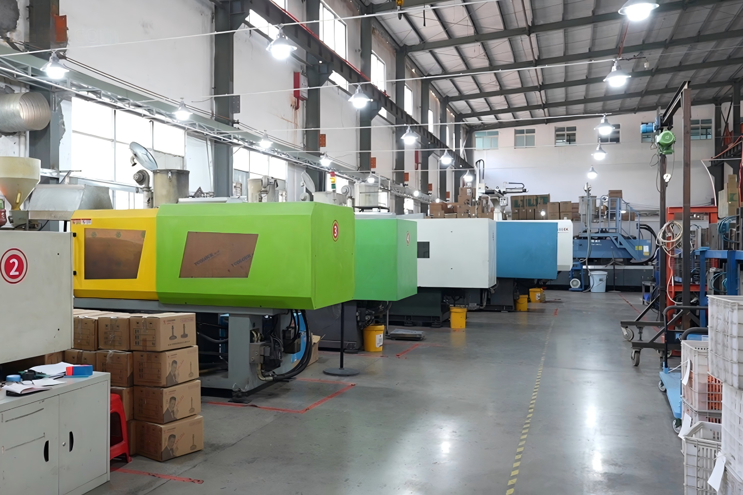
A practical note on the injection-molding and heavy equipment that often sits beside metrology areas: the vibration these machines generate is exactly the reason the testing station needs isolation rather than a rigid bolt-down. Matching the foot to its own environment, not to the machine next door, is what keeps measurement data trustworthy. During installation, do not skip the leveling procedure: set the feet near mid-stroke, level corner by corner with a spirit level, lock each foot, and re-measure once — ten extra minutes on the floor saves hours of rework later.
Plan the Whole Station, Not One Component
Real inspection workstations rarely rely on a single support element. Leveling feet handle leveling, mobile inspection tables pair casters with floor locks for transport and locking, and damping pads isolate environmental vibration. Each component manages one segment of the problem, and only together do they meet the requirements of a metrology environment. When equipment needs to be moved occasionally — for example, a portable inspection cart — a leveling caster that combines the wheel and the adjustable screw in one unit may be more practical than fixed feet plus separate casters.
Load capacity definitions and material grades differ between manufacturers, so confirm the standards clearly before procurement. Industrial support-component makers such as YTOP Manganese Steel Casters generally document per-foot load, stroke, base size, and material completely, which makes specification comparison straightforward. The measurement accuracy of testing equipment is built on a stable reference, and that is exactly what leveling feet are for: precision and vibration isolation take priority over price during selection, while leveling and locking matter equally during installation.
Related Reading
Looking for more in-depth caster guides and industrial mobility resources? Explore these related articles:
- Low Center of Gravity Casters — Stable and durable low-profile caster solutions ideal for precision testing equipment.
- What Is a Floor Brake? — Features and application scenarios of floor lock casters.
- What Problems Do Floor Locks Solve? — How floor locks prevent unintended movement during testing and calibration.
Explore our complete range of heavy-duty casters (150-610kg) and super heavy-duty casters (700-1600kg) for diverse industrial applications, or contact our engineering team for expert caster application knowledge and selection guidance.
Post time: Oct-10-2026