
Almost every caster sizing mistake starts with the same shortcut: add up the weight of the cart and the load, divide by four, and pick a caster rated just above that number. The arithmetic looks right and the result is often wrong by a factor of two. Four wheels do not share a load equally, and a static figure does not include the impact of a cart being pushed over a lip a hundred times a day.
This guide sets out a calculation method that holds up in practice: what weight to start from, how to estimate how the load is actually shared, how much to add for movement and floor condition, and how to check the answer on the equipment itself.
Start With the Weight the Equipment Really Carries
The number to start from is not the cart’s rated capacity and not the payload on the drawing. It is the fully loaded weight of the whole assembly, measured or estimated honestly.
Add four things together. The empty weight of the cart, rack or cabinet. The payload, at the maximum it will ever be, not the typical load. Any fixed equipment mounted on it: a pump, a motor, a battery pack, a hoist. And any accessories that are easy to forget, such as a shelf of tooling, a lid, or a collection bin hanging off one end.
It is worth weighing the loaded cart once if a platform scale is available. Workshop estimates are usually low by 10 to 20 percent, because the “typical” load gets remembered and the heaviest one does not. If the cart is part of a fleet that is loaded by different shifts, use the heaviest shift’s figure.
Why Four Wheels Rarely Share the Load Equally
Divide a perfectly rigid rectangle resting on a perfectly flat floor and the load does split evenly. Real equipment is neither. Three effects break the equality, and they compound.
Centre of gravity offset. Loads are rarely centred. A cabinet with drawers open at the front, a cart with a heavy bin on one side, a rack with a motor at one end: each moves the centre of gravity toward one corner. The two casters nearest that corner carry more, and the opposite corner can carry very little.
Floor flatness and structure deflection. Three casters will always find a plane; the fourth may carry almost nothing on an uneven floor, or the deck may flex so that one corner lifts. A cart with a flexible deck can behave like a three-wheeled trolley, which means three casters take the entire load.
Swivel geometry under load. When a cart is pushed, the swivel casters rotate and the load path shifts. In a cornering manoeuvre one caster often takes a temporary peak far above its static share.
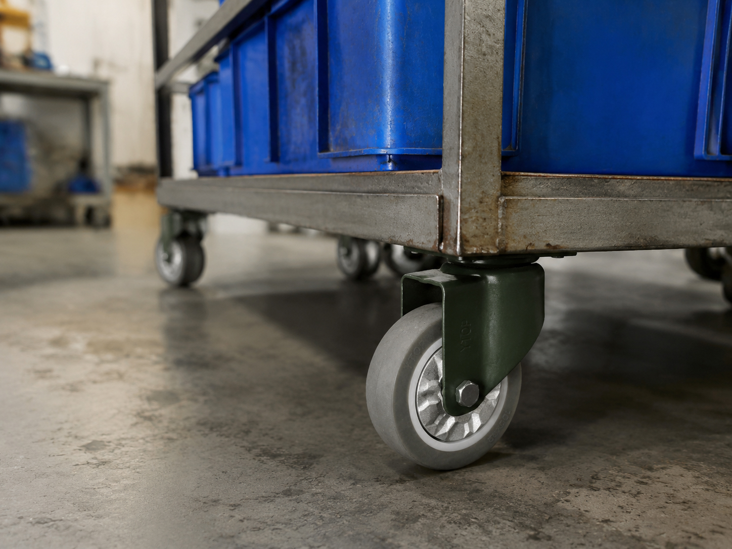
The practical conclusion used in industry is simple: for a four-wheel assembly, design each caster for at least one third of the total weight rather than one quarter. Where the centre of gravity is markedly off-centre, or the deck is flexible, assume the worst corner carries 40 to 50 percent.
Distribution Rules by Wheel Count
Three-wheel equipment behaves differently from four, and six-wheel equipment is usually not what it appears to be.
Three wheels. Three points define a plane, so all three share the load deterministically. You can calculate each wheel’s share from the centre of gravity position: draw lines from the CG to each wheel and the load divides in proportion to the geometry. This is the easiest case and the one where a calculation is most reliable.
Four wheels. Statically indeterminate once the floor is uneven or the deck flexes. Use the one-third rule as a floor, and the 40 to 50 percent rule for offset loads and flexible decks. Treat the diagonal pair as the critical case: if the CG sits near one corner, the diagonally opposite caster may carry under 10 percent and the nearest one over 40.
Six or eight wheels. Unless the frame is designed as a rigid beam system, only three or four wheels touch at any moment; the rest hang. Size each wheel as if only four were carrying the load, then check that the frame can actually distribute load to the others before assuming any sharing.
Tandem and triple-wheel assemblies. Two or three wheels on a common rocking axle split load between themselves, which is why they are used for heavy loads over uneven floors. Their combined capacity is not simply the sum of the individual ratings; use the manufacturer’s assembly rating.
Adding the Dynamic Factor
The static calculation tells you what the wheels carry when everything is standing still. The dynamic factor covers what happens when it moves, and this is where most under-specified casters fail.
Dynamic loads come from acceleration and braking, from rolling over thresholds and joints, from dropping off a curb or a tailgate, and from the shock transmitted through a rigid wheel on a rough floor. A reasonable working scale is:
- Smooth floor, gentle manual movement: 1.2 to 1.3 times the static figure.
- Occasional thresholds, joints or ramps: 1.4 to 1.5 times.
- Rough concrete, gravel, kerbs or drop-offs: 1.8 to 2.0 times.
- Towed or powered equipment at speed: higher still, and the assembly rating from the manufacturer should be used instead of a rule of thumb.
Multiply the two factors together and you have the design load per caster. Do not then subtract a margin because the number looks large; the calculation is already the minimum defensible figure.
A Worked Example
Take a four-wheel transfer cart weighing 120 kg empty, carrying 350 kg of parts, with a drawer bank that sits toward the front, so the centre of gravity is offset toward the front pair of wheels. The route crosses two expansion joints and a 12 mm threshold, on smooth concrete.
Total weight: 470 kg. Worst-corner share at 40 percent: 188 kg. Dynamic factor for thresholds: 1.5. Design load per caster: 282 kg.
That figure is already 60 percent of the total on a single wheel, which sounds extreme until you compare it with the one-quarter shortcut, which would have produced 117 kg and a caster rated at 150 kg. The 150 kg caster would be working at nearly double its rating at every threshold, and the failure would appear months later as a cracked fork or a collapsed raceway, far from the calculation that caused it.
Two further checks complete the selection. First, wheel diameter: the wheel still has to physically roll over the obstacle, and a 282 kg-rated 75 mm wheel will not cross a 12 mm threshold comfortably no matter how strong its bracket is. Second, bearing type: a plain bushing can carry the load statically but wears quickly under dynamic peaks, so a roller or ball bearing is the right choice once the dynamic factor is above about 1.4.

Verify the Calculation on the Equipment
A calculation is a model, and models get the centre of gravity wrong. Twenty minutes with a bathroom scale, or four load cells if the cart is very heavy, will show you the real distribution.
Load the cart as it will actually be used, put one wheel on a scale at a time while the other three rest on blocks of the same height as the scale, and record each corner. Then move the load to the worst position you can imagine: drawers open, bin full, heaviest part at the far end. The highest corner reading, multiplied by the dynamic factor, is your true design load.
If the readings are wildly unequal, the fix is often not a bigger caster but a layout change: move the heavy item toward the centre, add a fifth support, or stiffen the deck. Casters are the last item in the chain, not the first.
Four Mis-Specifications That Repeat Every Week
The same four errors account for most of the load-related caster failures we are asked to diagnose.
Using the cart’s rated capacity instead of the loaded weight. A cart rated for 500 kg may never carry more than 300 kg, but a cart rated 200 kg is often loaded to 350 kg because nobody weighs the load. The rating describes the frame, not the moment-to-moment reality.
Dividing by the number of wheels instead of the number carrying. Six-wheel equipment frequently has only four wheels on the floor, and a flexible deck reduces a four-wheel cart to three effective supports. Dividing by the number printed on the layout drawing overstates capacity by 30 percent or more.
Ignoring where the load sits. A rack with a motor at one end behaves like a two-caster machine at that end. The right response is either a heavier caster at the loaded end or a layout change that brings the mass back toward the centre.
Treating static ratings as dynamic ratings. Capacity figures are usually quoted for a stationary load on a flat floor. A cart crossing a 15 mm threshold at walking pace can see twice the static load for an instant, and that instant is what cracks a fork leg or flattens a bearing raceway.
A useful discipline is to write the four numbers down before ordering: loaded weight, worst-corner share, dynamic factor, and design load per caster. If the last number is larger than the caster’s rated capacity, the specification is wrong regardless of what the catalogue page says.
Sizing Checklist
Before ordering, confirm: the fully loaded weight including accessories; the number of wheels that actually touch the floor; the worst-corner share, based on CG position and deck stiffness; the dynamic factor for the route and the way the cart is moved; and the wheel diameter needed for the floor’s obstacles. Then compare the resulting design load with the caster’s rated capacity at the intended speed and duty cycle, not just its static rating.
If you send us the loaded weight, the wheel layout and a description of the route, we will return a per-caster figure and a matched wheel and bearing specification.
Related Reading
Two guides that go deeper on the two inputs to this calculation, capacity and tread:
- What Factors Affect Caster Load-Bearing Capacity — the material, structure and bearing factors behind a rated figure.
- Caster Tread Hardness: Shore A and Shore D Selection Guide — how tread hardness changes the load the wheel can carry and the floor it protects.
Explore our heavy-duty casters (150-610kg) and super heavy-duty casters (700-1600kg) for multi-wheel assemblies, or contact our engineering team with your loaded weight and wheel layout for a per-caster calculation.
Post time: Nov-12-2026